Driving a Continuous Rotation Servo with PCA9685 16-Channel PWM Driver using Raspberry Pi
Table of Contents
- Useful Links
- Proof of Purchase
- Header Soldered
- I2C Wiring
- I2C Detected
- Changing the PCA9685 Address
- PCB Design
- Schematic Diagram
- Video of Working Servomotor
- Enclosure
- Final View
- Presentation
Useful Links
CENG 320 Page | GitHubpage
Week 1 | Week 2 | Week 3
Week 4 | Week 5 | Week 6
Week 7 | Week 8 | Week 9
Week 10 | Week 11 | Week 12
Week 13 | Week 14 | Week 15
Presentation
Week 13 - Nov. 27, 2018
Due today:
Presentation
The PowerPoint presentation can be obtained here
Week 12 - Nov. 20, 2018
Due today:
Enclosure
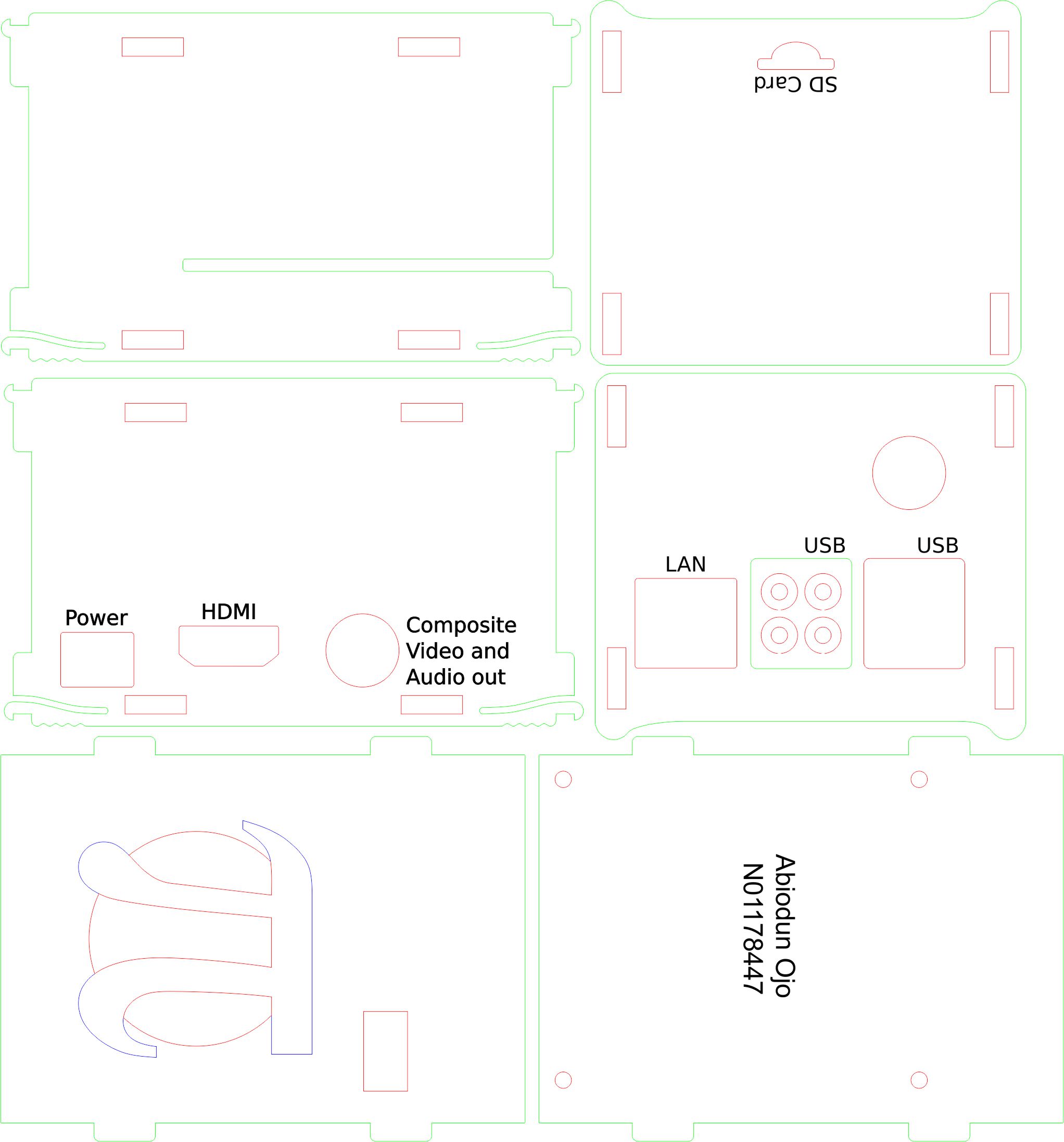
The enclosure was designed in Corel Draw which is not free for use. The college, however, have it installed in the lab for student use. Accurate measurement has to be made and the design file modified accordingly to fit the Raspberry and the Broadcom Development platform. The design can be downloaded here for modification.
Assembled Enclosure:
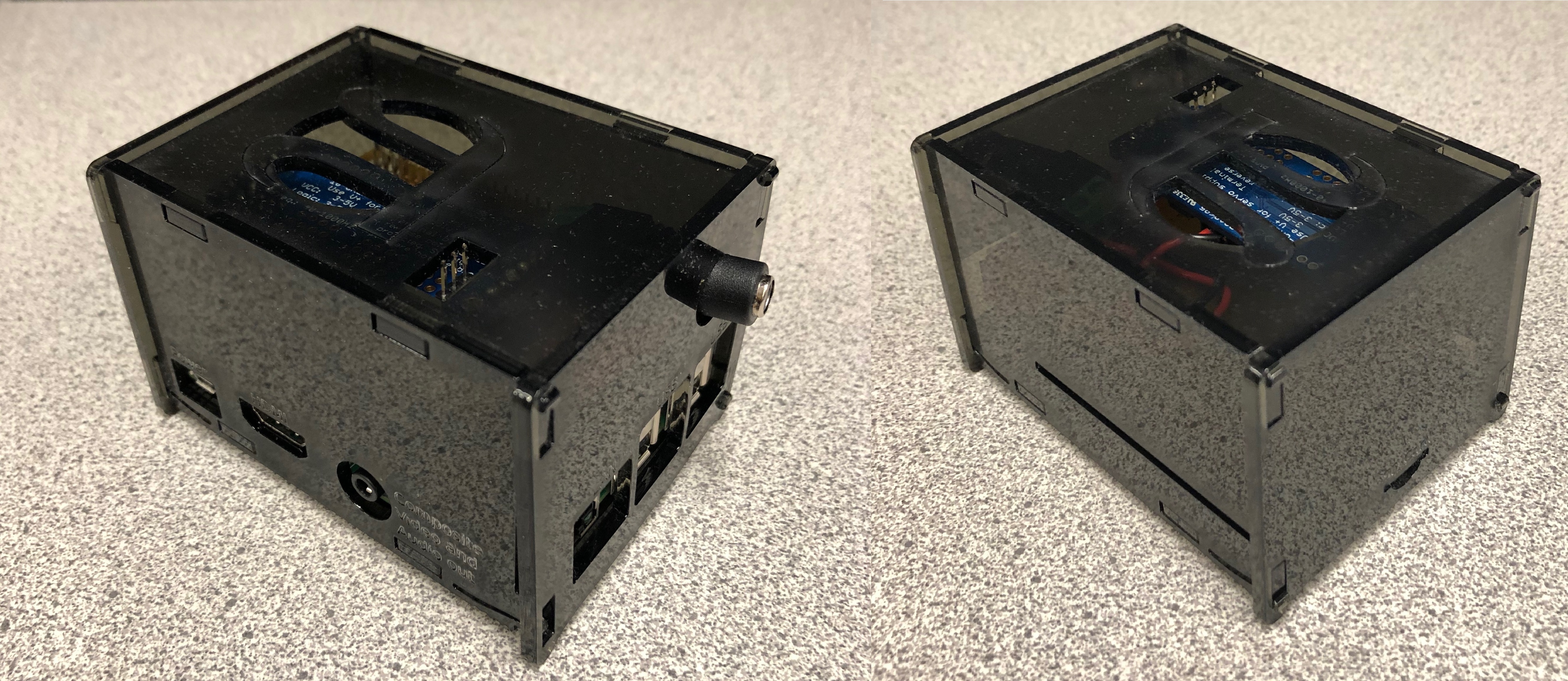
Video Enclosure
Enclosure Design
Week 11 - Nov. 13, 2018
Due today:
Powerup
Progress Report:
The project is on track according to the project timeline, I was able to achieve power up since last week. No additional cost incurred since the last purchase.
I demonstrated the power up to the professor in class. Video is posted here.
Week 10 - Nov. 6, 2018
Due today:
PCB soldered
Progress Report:
The project is on track according to the project timeline. I made additional expenses to buy pin and stackable headers at Creatron which made the project’s budget to be a little over the budget by $9.29 plus time and mileage.
So far, I have been able to connect my PCB to the Raspberry Pi and the servomotor controlled successfully.
Video
Week 9
Status Update
Additional parts Pin Headers have been purchased so the project is a little over the budget by $9.29.
The project is on track according to the project timeline.
PCB Design
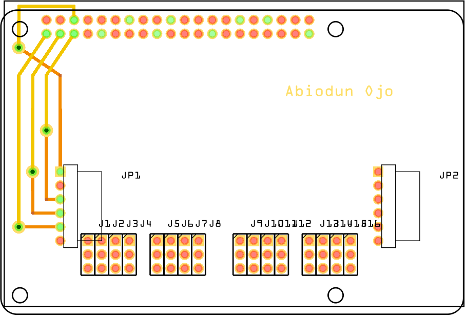
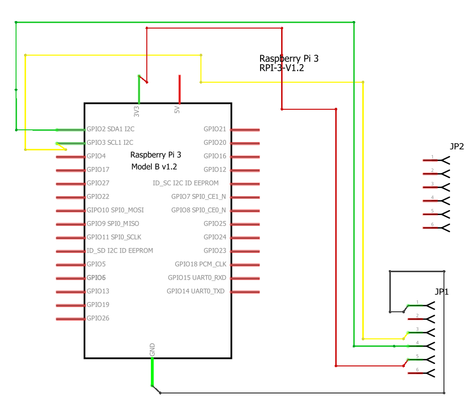
I used the free software Fritzing to make the Schematic Diagram and the PCB design as shown in the images below.
After the design, the fritzing file was exported as an extended grubber file and emailed to the Humber Prototype Lab in order to manufacture the PCB.
Pin Headers
Pin headers are required for connecting the I2C (PCA9685) to the PCB and also to stack the PCB to the Raspberry Pi.
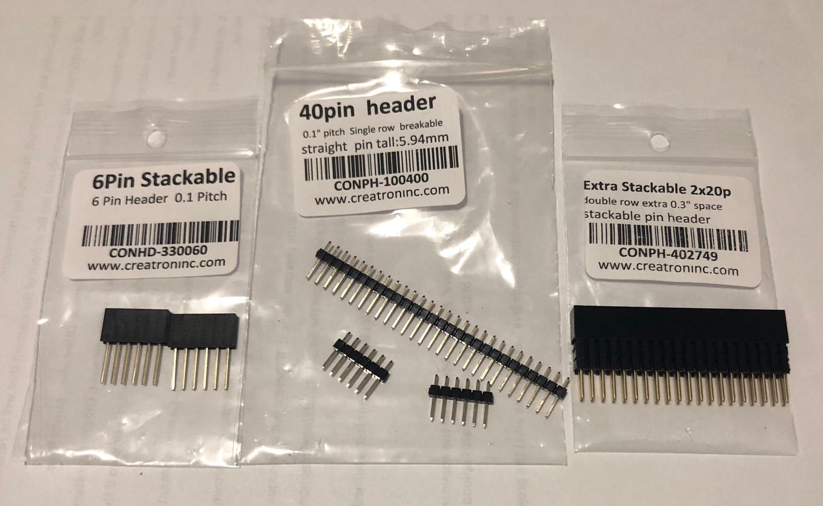
The following pin headers were purchased:
- 6Pin Stackable(CONHD-330060) - This will be soldered to the PCB and the PCA9685 will be mounted on it.
- 40pin header (CONPH-100400) - This is breakable to required number of pin headers. I broke out 2 X 6 pins, to solder to the PCA9685 to serve as connection and support for the PCA9685 on the PCB.
- Extra stackable 2 x 20p (CONPH-402749) - This will be soldered to the PCB to extend the Raspberry Pi3 40 pins out of the PCB.
PCB Design
Schematic Diagram
Week 8
Changing PCA9685 Address
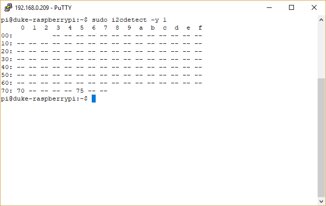
For this project, I have been assigned address 0x75. The PCA9685 default address is 0x40. Below are the steps in changing the address.
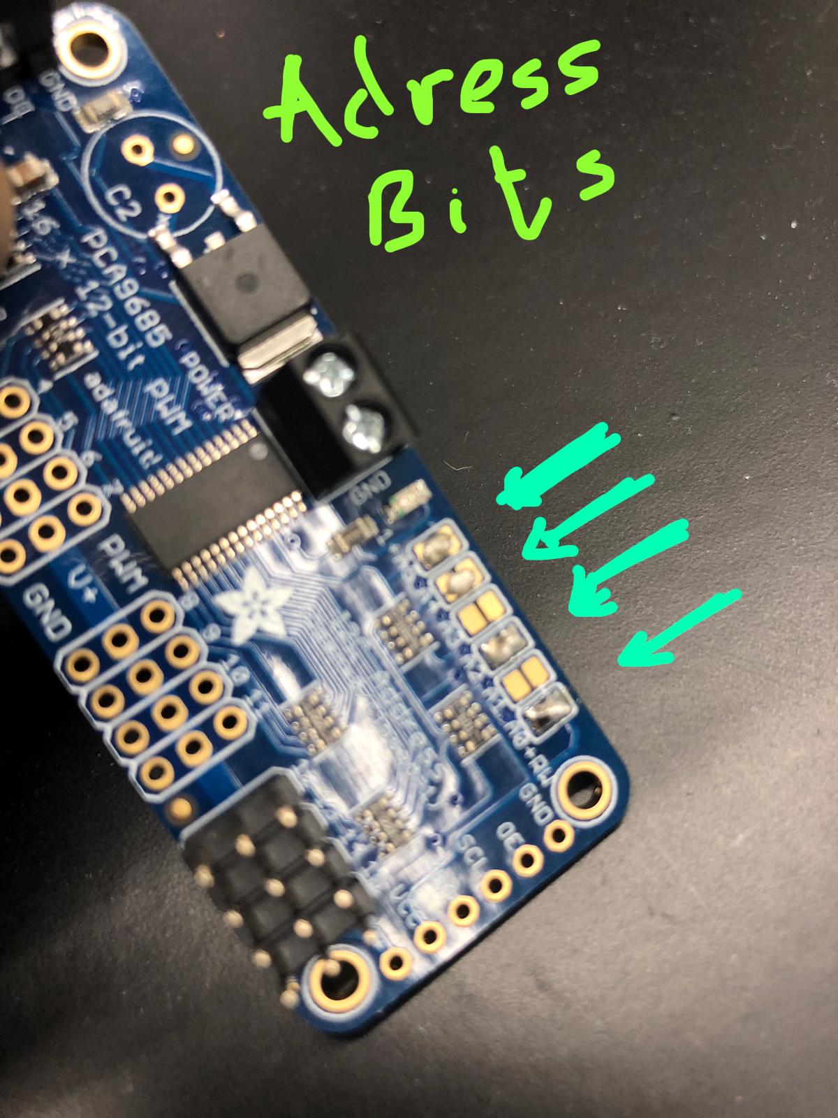 There are six address bits (labeled A0 to A5, A0 being the least significant bit (LSB)) on the board that are turned off by default. The addressing starts at 0x40 (Hexadecimal) which in Binary is 0100 0000. To get 0x75 as the address, the address bits will have to be turned on by soldering a piece of solder to bridge the plates, hence turning on the bits.
0x75 in Binary is 0111 0101. To achieve this, I put solder on A0, A2, A4, and A5.
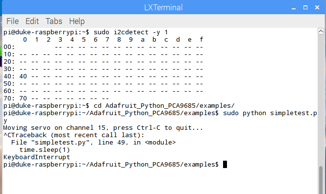
Below is the screenshot showing the new address.
I2C To RPi Wiring
Wiring
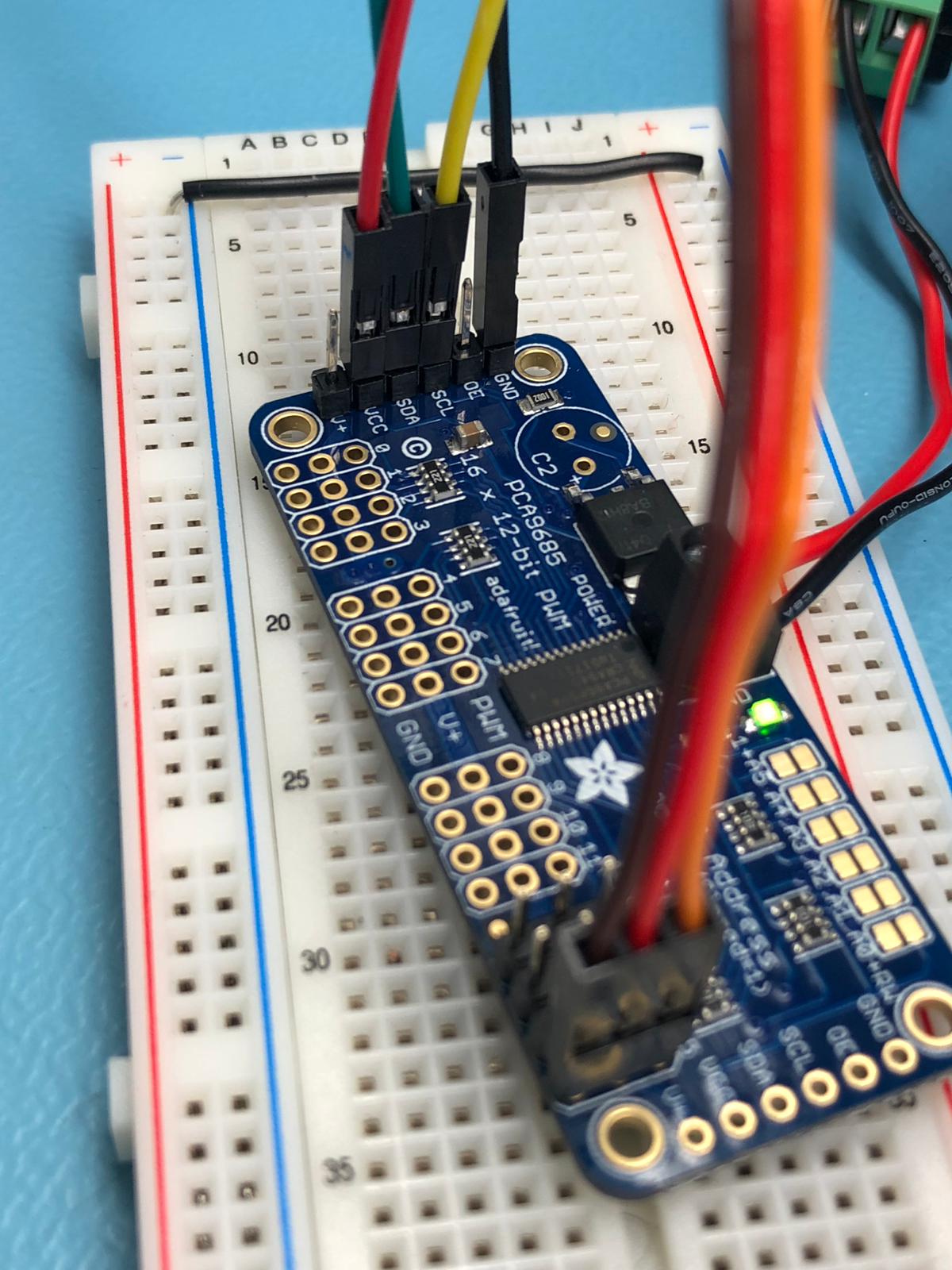
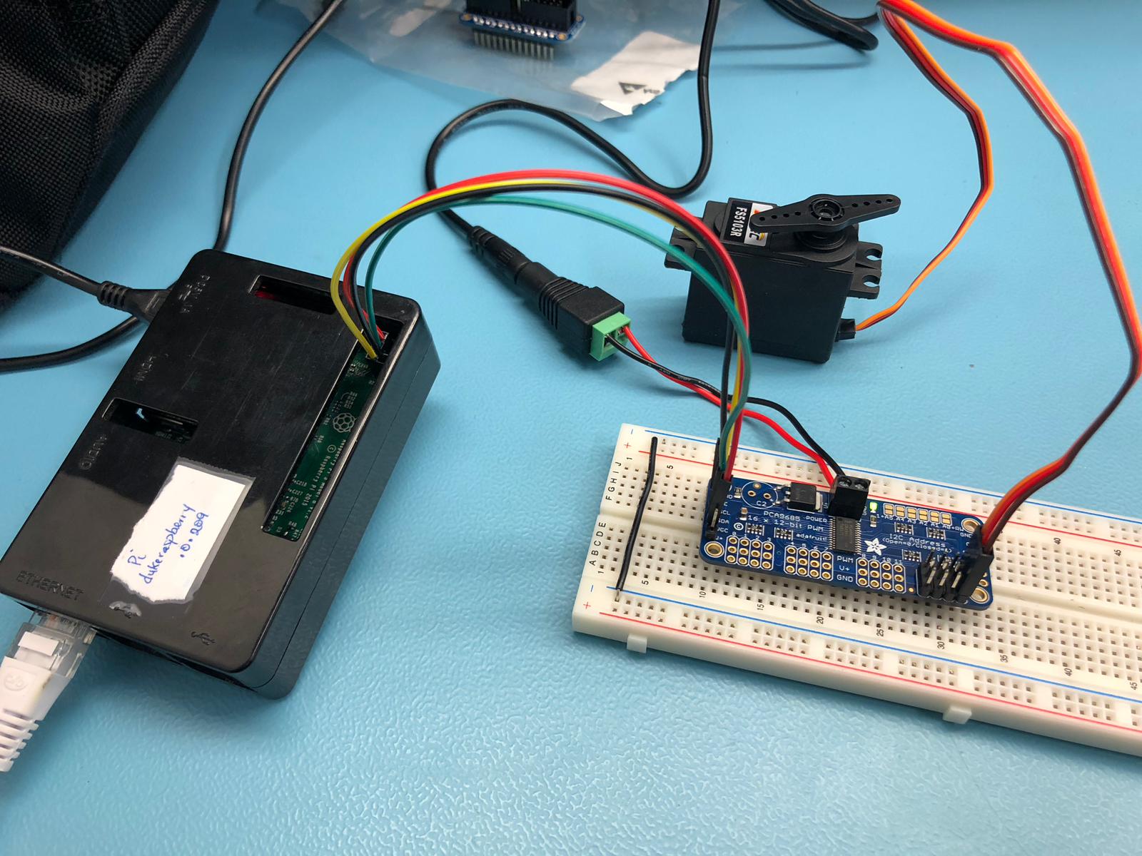
The I2C Device PCA9685 can drive up to 16 Sevo Motors since it has 16 channels. In the above connection, I only used one continuous rotation servo motor for testing purpose (to show that the RPi can detect the I2C and run the motor using the Python code posted below. The RPi pinouts can be found RPi Pinouts.
Because of the RPi fluctuating voltage levels, it is advised to power the servo motor by a separate +5V source (there is provision for the connection on the I2C). The I2C (PCA9685) itself is powered from the the 3.3V output of the RPi.
I connected I2C’s VCC and GND to pins 1 and 6 respectively on the RPi. The Serial Clock (SCL) and Serial Data (SDA) were connected to pins 5 (BCM 3 - Clock) and 3 (BCM 2 - Data) of the RPi respectively. I connected one servo motor to channel 15 of the PCA9685 (Orange side to the PWM, Red to the V+, and Brown to GND). I made some modifications to the sample code provided by Adafruit
Sample Code
# Simple demo of of the PCA9685 PWM servo/LED controller library.
# This will move channel 15 from min to max position repeatedly.
# Author: Tony DiCola
# Edited by Abiodun Ojo
# License: Public Domain
from __future__ import division
import time

# Import the PCA9685 module.
import Adafruit_PCA9685


# Uncomment to enable debug output.
#import logging
#logging.basicConfig(level=logging.DEBUG)

# Initialise the PCA9685 using the default address (0x40).
pwm = Adafruit_PCA9685.PCA9685()
# Alternatively specify a different address and/or bus:
#pwm = Adafruit_PCA9685.PCA9685(address=0x41, busnum=2)
# Configure min and max servo pulse lengths
servo_min = 150  # Min pulse length out of 4096
servo_max = 600  # Max pulse length out of 4096

# Helper function to make setting a servo pulse width simpler.
def set_servo_pulse(channel, pulse):
pulse_length = 1000000    # 1,000,000 us per second
pulse_length //= 60       # 60 Hz
print('{0}us per period'.format(pulse_length))
pulse_length //= 4096     # 12 bits of resolution
print('{0}us per bit'.format(pulse_length))
pulse *= 1000
pulse //= pulse_length
pwm.set_pwm(15, 0, pulse)

# Set frequency to 60hz, good for servos.
pwm.set_pwm_freq(60)

print('Moving servo on channel 15, press Ctrl-C to quit...')
while True:
# Move servo on channel 15 between extremes.
# pwm.set_pwm(15, 0, servo_min)
#   time.sleep(1)
#    	pwm.set_pwm(15, 0, servo_max)
#    	time.sleep(1)

pwm.set_pwm(15, 0, 10) # Rotate
	time.sleep(1) #Sleep
pwm.set_pwm(15, 0, 0)  #Do not rotate
time.sleep(1)
I2C Connected to the RPi
Week 7
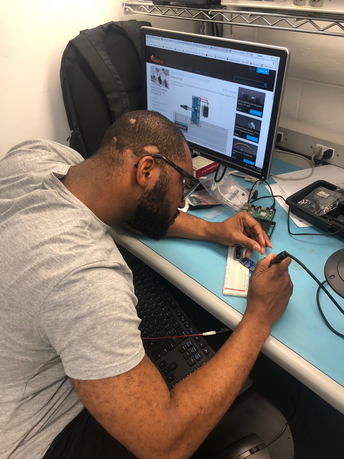
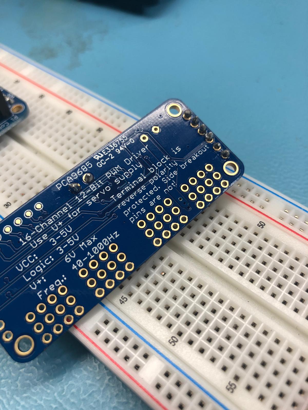
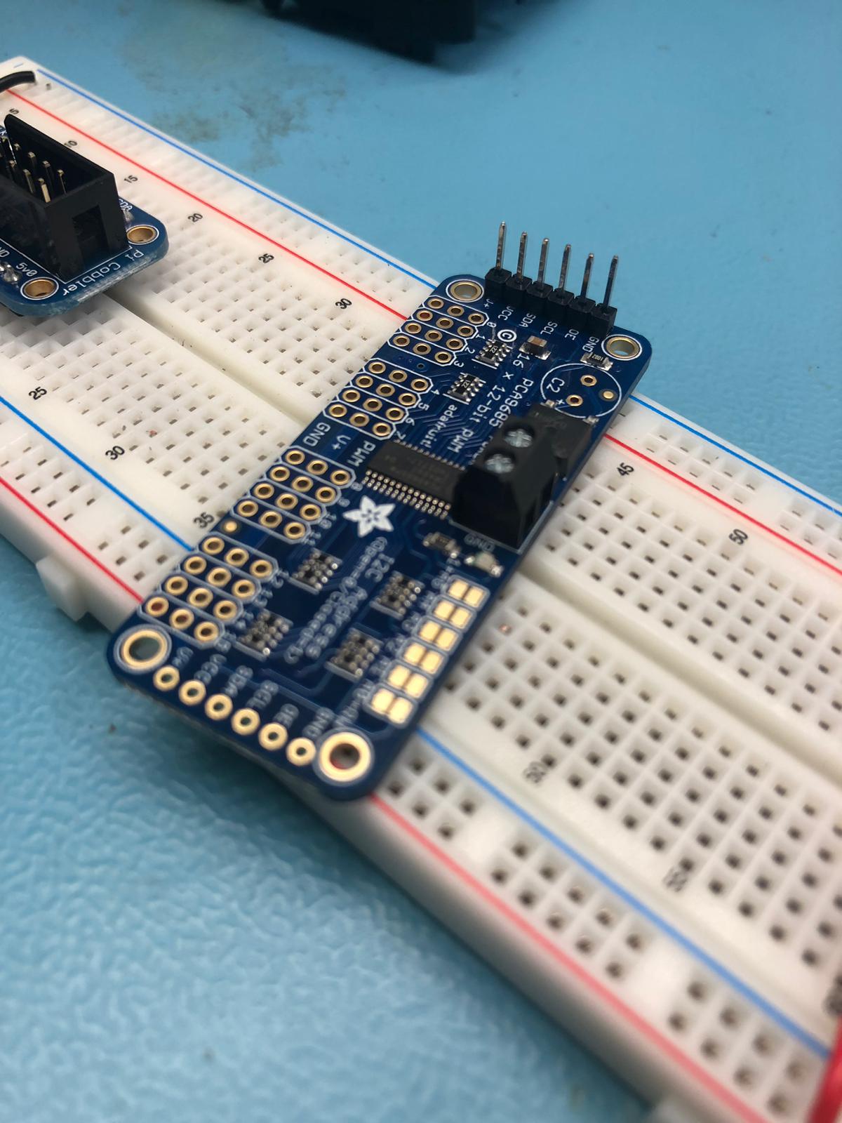
Soldered the Header
Week 6
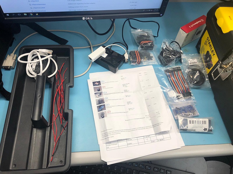
Proof of Purchase
